
PSI Hydraulic Power Units – Configuration and Operation
PSI Hydraulic Power Units
PSI utilizes hydraulic systems to control our screen changers and divert valves. The hydraulic system employs enclosed fluid to transfer energy from the hydraulic power unit to the machine-mounted hydraulic cylinder and creates a linear motion or force. Hydraulic power units apply the pressure that drives the motion of the hydraulic cylinders. Unlike standard hydraulic pumps, these power units use multi-stage pressurization networks to move fluid in different cylinders. Some of the important factors that influence a hydraulic power unit’s performance are pressure limits, power capacity, and reservoir volume. In addition, the physical characteristics, including size, power supply, and pumping strength are also significant considerations. To better understand the operating principles and design features in a hydraulic power unit, it may be helpful to look at the basic components of a standard model used in industrial hydraulic systems.
PSI hydraulic power units are built to function under industrial conditions and have design characteristics distinct from a typical pumping system. Standard design features include:
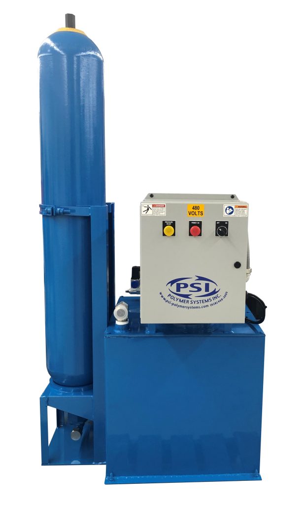
Accumulators (used for HSC and CSC-BF hydraulic systems): These are vessels attached to the hydraulic actuators. They contain pressurized nitrogen to be released when intended for an extremely fast cylinder shift.
Motor Pumps (used on all PSI hydraulic systems: A hydraulic power unit can be equipped with a single motor pump, or multiple devices each with their own accumulator valves.
Tanks: The tank is a storage unit designed with enough volume for the fluid in the pipes to drain into it. These are used for ALL hydraulic systems.
Filters: A filter is typically installed along the top of the tank in the return line for removing trash from the system. These are used for ALL hydraulic systems.
Power Unit Controllers: The hydraulic controller unit is the operator interface containing power switches, displays, and monitoring features. It is necessary for installing and integrating a power unit into our hydraulic systems, and can usually be found wired into the power unit. PSI will typically provide an Electromechanical Control Box (ECB) for manual actuation or a Programmable Logic Controller (PLC) for automatic actuation. These are used for ALL hydraulic systems with multiple cylinders or multi-stage pressurization networks.
Control Valves: Different control valves are mounted to the hydraulic unit to control the hydraulic cylinders. For every cylinder required for actuation, one direction control valve is required to operate and send fluid to the cylinder from the hydraulic power unit. The “Power Unit Controller” selects which control valve to operate and either allows the cylinder to extend or retract, depending on the direction selected. These are used for ALL hydraulic systems.
When a hydraulic power unit begins functioning, the following happens:
- The power is turned on.
- For a CSC hydraulic power unit, once the hydraulic power unit is actuated by the controller, the gear pump pulls hydraulic fluid out of the tank and moves it to the corresponding cylinder.
- For a HSC hydraulic power unit, the gear pump pulls hydraulic fluid out of the tank and moves it into an accumulator after the power is turned on. This process continues until the pressure within the accumulator reaches a predetermined level.
- Pressure switches are used to regulate accumulator pressure.
- Once the pressure is reached, the unit is ready for an immediate actuation. Once the hydraulic power unit is actuated by the controller, the accumulator sends hydraulic fluid out of the tank (accumulator.. not the tank) and moves it to the corresponding cylinder immediately for a fast shift.